
For existing problems such as transverse cracks in the bottom slabs of prestressed concrete beams, external prestressed steel bundles, prestressed carbon fiber boards, etc. are generally used for active reinforcement. However, identifying the degree of bridge damage, controlling the reinforcement process, and evaluating the reinforcement effect are crucial to ensuring that the bridge reinforcement project achieves the intended design.
As a commonly used method, load testing cannot continuously monitor the bridge reinforcement process and has high costs and significant impacts. Bridge reinforcement engineering accompanied by monitoring technology enables continuous monitoring of key response parameters of the reinforced bridge without interrupting traffic, providing real-time guidance for external bundle tensioning construction and ensuring the reinforcement effect.
Problems Encountered in Bridge Reinforcement Process
The current objective situation, such as the significant impact of high-speed traffic, difficulty in closing traffic for load testing, and unknown permanent prestress in internal prestressed steel bundles of the beam body, makes it difficult to accurately assess the degree of damage to the structural load-bearing capacity, leading to an inability to accurately determine the required degree of prestress reinforcement.
During the bridge reinforcement process (especially for active reinforcement schemes such as external prestressing), due to the influence of various unknown factors, model simulations cannot accurately calculate the actual situation of the bridge. It is difficult to determine the required degree of reinforcement (such as the determination of the control force for tensioning the external bundle) for the damaged bridge, and controlling the tensioning process is extremely important, as there is a risk of structural damage or even collapse.
After the reinforcement is completed, traditional methods of evaluating the reinforcement effect, such as load testing, require closing traffic, resulting in significant social impact and high costs. Additionally, these methods only provide a detection conclusion for a specific point in time after the reinforcement. Therefore, an evaluation method that does not interrupt traffic, is economically reasonable, and can continuously reflect the reinforcement effect is of utmost importance.
Purpose of Accompanying Monitoring
Before Reinforcement- Estimate the degree of structural damage
By employing an indirect evaluation method that does not require closing traffic, monitoring is conducted at the same positions on structurally similar (span length, beam structure, etc.) intact bridge spans. The structural responses (strains, deformations, etc.) under loading (natural vehicle traffic) are compared, and any differences are analyzed to estimate the degree of structural damage.
During Reinforcement- Control the reinforcement process
During the bridge reinforcement construction process, dynamic monitoring is carried out, and the tensioning force of the external bundle is adjusted in real-time based on the experimental data, providing technical basis for determining the control stress of the external bundle tensioning and identifying the performance after bridge reinforcement and repair.
After Reinforcement- Evaluate the reinforcement effect
By comparing the structural responses (cracks, strains, deformations, etc.) before and after reinforcement, as well as the structural responses (cracks, strains, deformations, etc.) between the reinforced span and the test comparison span after the reinforcement is completed, the actual reinforcement effect is summarized, and an overall evaluation of the bridge structure reinforcement effect is made.
Principle and Technical Route
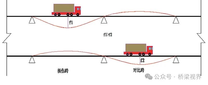
Structural response monitoring points are set at the same positions on bridge spans of the same type (span length, bridge structure, reinforcement, etc.). Under the same traffic environment and vehicle loading conditions (same speed, same weight), the structural responses (cracks, strains, deformations, etc.) are collected. In terms of structural performance responses, the bridge span with more severe structural cracks performs worse than the span without significant damage and in good technical condition.
By statistically analyzing the structural response values from a large number of vehicle passages, the damaged span, the span in good technical condition, and the theoretical model data are compared and analyzed for differences, allowing the estimation of the degree of structural damage. Dynamic monitoring is carried out during the reinforcement construction process, and the reinforcement construction is guided based on the experimental data to precisely control the tensioning force of the external bundle, ensuring the desired effect is achieved.
Accompanying Monitoring System
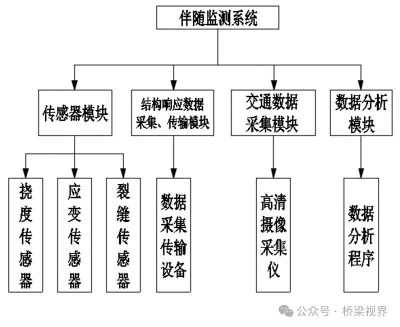
The accompanying monitoring system mainly includes a sensor module, a data acquisition and transmission module, a traffic data acquisition module, and a data analysis module.
Sensor module – Digital automatic high-frequency sensors for temperature, humidity, deflection, strain, cracks, etc., are installed at various monitoring sections of the bridge.
Data acquisition and transmission module – When vehicles pass through, the deflection, strain, and crack responses of the bridge structure are automatically and rapidly collected and transmitted to the data analysis program.
The traffic data acquisition module continuously collects high-definition data on vehicles passing over the bridge deck, with each vehicle’s passage corresponding to the structural response.
The data analysis module organizes, compares, and analyzes the data from each collected time period for the reinforced span and the comparison span. During data analysis, combining the traffic data, data without interference from other vehicles or overtaking incidents on the bridge is selected, and data with multiple vehicle interference is excluded to ensure consistent vehicle loading between the reinforced span and the comparison span.
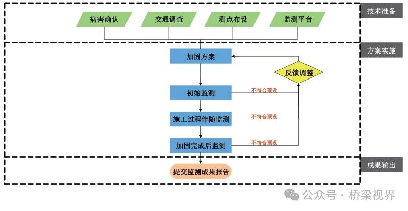
Implementation Process of Accompanying Monitoring
Monitoring Point Layout
Based on the internal force envelope diagram and damage occurrence of the bridge structure, the reinforced span and comparison span are selected. The reinforced span is the damaged span, and the comparison span is selected as a structurally similar (span length, beam structure, etc.) intact bridge span. Typical control sections (such as mid-span sections, support sections) are determined, and deflection, strain, crack, and other structural response monitoring points are installed. The monitoring point locations and layout methods are the same for the test span and the comparison span, with sensors having a frequency of no less than 20 Hz, and an accompanying monitoring platform is established.
Monitoring Before Reinforcement
Under natural traffic conditions, the monitoring time period is determined based on the traffic volume and composition. The structural responses (deflection, strain, etc.) of the reinforced span and the comparison span are continuously observed when vehicles, especially heavy vehicles, pass through. The structural responses (strains, deformations, etc.) of the reinforced span and the comparison span under natural vehicle traffic loads are compared, and any differences are analyzed to estimate the degree of structural damage and initially adjust the reinforcement scheme (e.g., for a combined reinforcement scheme of external prestressed carbon boards and external prestressed steel bundles, the initial damage results are used to determine the secondary reinforcement measure – the tensioning control stress of the external prestressed carbon boards).
Monitoring During Reinforcement
The external bundle is tensioned symmetrically in stages, and the structural responses (stresses, deflections, cracks, etc.) at the control sections are continuously monitored during the tensioning process. The results before and after reinforcement of the reinforced span, as well as the results between the reinforced span and the comparison span, are compared and analyzed to provide real-time guidance for the tensioning level.
The final tensioning control stress is determined by a three-fold control of deflection, strain, and cracks, and must meet the following conditions:
- Under the same heavy vehicle passage condition, the deflection increment of the reinforced span is smaller than the deflection increment of the comparison span.
- Stress main control indicator: After external prestress tensioning, the reserved compressive stress value in the beam bottom (stress increase caused by external bundle tensioning) is greater than the theoretical calculated tensile stress value caused by the design vehicle load or the normal service state vehicle load.
Stress auxiliary control indicator: Under the same heavy vehicle passage condition, the stress increment of the reinforced span is smaller than the stress increment of the comparison span. This auxiliary condition is only applicable when the beam has fewer cracks, the stress release under heavy loads is relatively uniform, and the stiffness of the structure can be reflected.
- Cracks: The original cracks are closed, and under normal traffic conditions, the original cracks do not open under the reinforcement prestress.
- If the structural responses (stresses, deflections, cracks, etc.) exhibit rapid growth or values exceeding the theoretical values during the tensioning process, the tensioning process should be terminated immediately.
Monitoring After Reinforcement
After the reinforcement is completed, continuous monitoring is carried out at the structural response monitoring points of the reinforced span and the comparison span without interrupting traffic (the monitoring duration is determined based on the actual traffic volume and composition, combined with the characteristics of the reinforcement scheme). The structural responses (cracks, strains, deformations, etc.) before and after reinforcement, as well as the structural responses (cracks, strains, deformations, etc.) between the reinforced span and the comparison span after the reinforcement is completed, are statistically compared and analyzed. The actual reinforcement effect is summarized, and an overall evaluation of the bridge structure reinforcement effect is made.
Engineering Case Study
A 4×25m prestressed concrete continuous beam bridge experienced transverse cracks in the second span, and prestressed carbon boards and external prestressed steel bundles were used for reinforcement.
An intact span and a damaged span were selected as the comparison span and the reinforced monitoring span, respectively. Deflection and strain monitoring points were installed at the mid-span section, and crack monitoring points were installed at the transverse cracks on the bottom slab.
Continuous monitoring of cracks, strains, and deflections was carried out before, during, and after reinforcement, and bridge deck traffic and vehicle flow data were collected during the respective monitoring time periods.
Analysis of Monitoring Results
- Crack Monitoring Result Analysis
Before the bridge reinforcement, most heavy vehicles caused changes in the crack width, with relatively large values. After the reinforcement was completed, the crack values were zero for most vehicles passing through. For a few heavy trucks or multiple trucks traveling in parallel, the crack values showed some fluctuations, but the values were very small, with a maximum crack value of 0.002mm, which was actually a reaction to strain. It can be seen that after the reinforcement was completed, the load-bearing performance and durability of the bridge were significantly improved. Under normal vehicle loads (not overloaded) when traffic is normal, the entire cross-section of the beam participates in load-bearing, and the original cracks do not open under the reinforcement prestress.
| Monitoring Period | Vehicle Type | Vehicle Statistics/Vehicle | Number of Fluctuations/Time | Number of Times Over 0.01/Time | Crack Change Amount △ Maximum Value/mm |
|---|---|---|---|---|---|
| Before Reinforcement | Overload Truck | 44 | 31 | 20 | 0.02 |
| Before Reinforcement | Bus | 12 | 0 | 0 | 0 |
| After Reinforcement | Overload Truck | 87 | 15 | 0 | 0.002 |
| After Reinforcement | Bus | 14 | 0 | 0 | 0 |
- Strain Monitoring Result Analysis
For all monitoring periods, the strain values caused by actual passing vehicles were statistically analyzed, with the maximum strain increment being 48.5με. The compressive strain (increment) produced by the external bundle prestress was compared with the tensile strain caused by the vehicle load, as shown in Table 2. The external bundle produced a prestress of 1.84 MPa at the bottom of the reinforced span beam, which is greater than the maximum tensile stress of 1.56 MPa caused by the observed vehicle load.
| Item | Prestress | Maximum Traffic Load | Reserve Margin |
|---|---|---|---|
| Strain/με | -57.17 | 48.5 | -8.67 |
| Stress/MPa | -1.84 | 1.56 | -0.28 |
Therefore, it can be inferred that after the bridge reinforcement is completed, under normal traffic flow conditions, the beam bottom will not experience tensile stress when regular vehicles (not overloaded) pass through under the action of the reinforcement prestress.
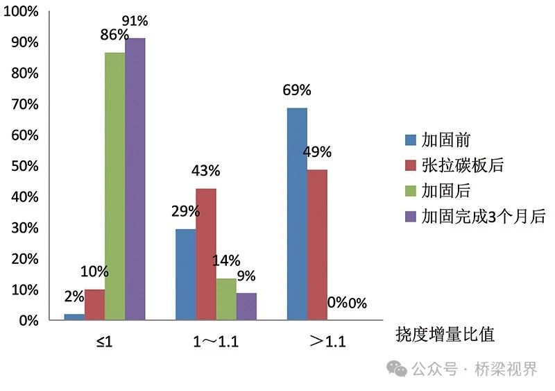
- Deflection Monitoring Result
After the bridge reinforcement was completed, the structural stiffness was significantly improved. The average deflection increment ratio (reinforced span/comparison span) was significantly smaller than before reinforcement and after tensioning the carbon board, with the majority (91%) of values being less than 1, indicating that the stiffness of the reinforced span reached the stiffness of the comparison span.
In the accompanying monitoring work during the bridge reinforcement process, the main roles were as follows:
Firstly, under the condition of uninterrupted traffic, the bridge reinforcement process was continuously monitored, and according to the analysis of the crack, strain, and deflection data from the accompanying monitoring, the load-bearing performance, structural stiffness, and durability of the bridge were significantly improved after the reinforcement was completed.
Secondly, after the reinforcement was completed, when the traffic flow was normal, under regular vehicle loads, the entire cross-section of the beam participated in load-bearing, and the original cracks did not open under the reinforcement prestress. The beam bottom did not experience tensile stress under the action of the reinforcement prestress, indicating that the reinforcement achieved the intended effect and can meet the load-bearing requirements under the original design load standard.
This article was published in the “Bridge Maintenance and Operation” magazine 2023, Issue 4, Total Issue 24 Author: Meng Tao, Zhao Qingyun Author’s affiliation: Shandong Transportation Planning & Design Institute Group Co., Ltd.